raghu@isysindia.com 08069247353 Ext : 210
Check Weighing Scale PCB
| Business Type | Manufacturer, Supplier, Retailer, Wholesaler |
| No. of Relay | 3 |
| Quality | Superior |
| Usage | Industrial |
| Click to view more | |
Preferred Buyer From
| Location | Anywhere in India |
Product Details
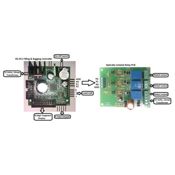
The Kit contains the following items
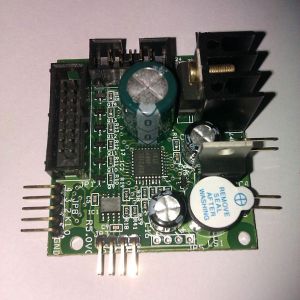
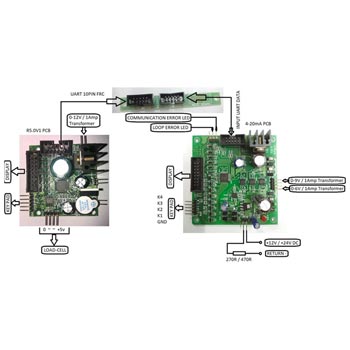
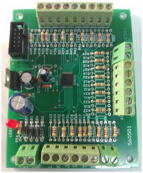
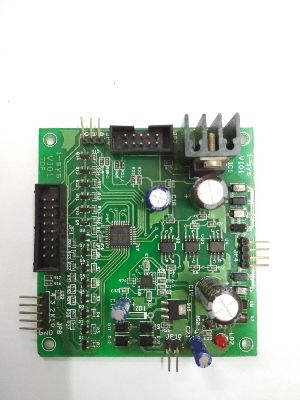
- Check Weighing Controller PCB R5.0V1 – 1no.
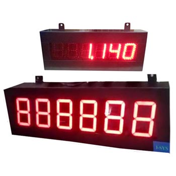
- 0.56” Red display – 1nos.
- 4-input Keypad with connector – 1nos.
- Optically Isolated Relay PCB – 1no.
- 0-12V/1Amps transformer – 2no.
- 0-15V/1Amps transformer – 1no.
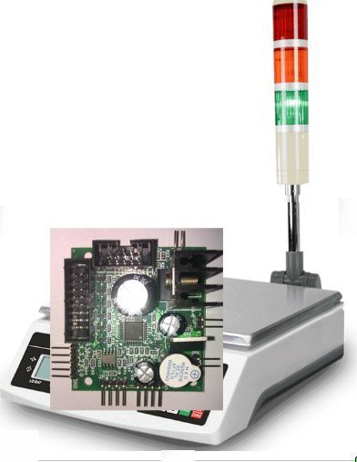
The check weighing system provides 3-relay output for indicating 3 weighing regions. They are the low weight, normal weight & high weight. You can connect tower lamps & buzzer alarms to the appropriate relay output for visual & audio annunciation. Two set-point values are needed to be entered in the controller for creating the three zones.
Calibration of Check Weighing PCB : The calibration procedure for check weighing PCB is similar to R5.0V1 weighing scale PCB.
Parameter settings in Check Weighing
Controller PCB : Please set the “PSEL” value in (“PARA”) the parameter setting to “1” to activate the set-point or check weighing functionality.
Our Check Weighing PCBs are designed using advanced industrial grade 16bit Renesas microcontrollers. They are used for accurate and fast weighing and checking of packaged commodities in a process plant and in a production line. RS232 interface to the check weighing PCB allows for data logging & printing of packing weight information. Customized programming to suit user specific relay control outputs can also be delivered.
HOW TO ENTER THE SET-POINT VALUES ?
Once the calibration & parameter setting procedure is completed, you can switch OFF & ON the Controller PCB. If no set-point value is entered in the controller, the controller will indicate “Enter Set Point” as a scrolling display. Now, press TARE key (K4) and SHIFT key (K3) simultaneously. The display will blink & then show “SET-1” for a brief period as shown below…
| S | E | T | - | 1 |
Next it shows…
| 0 | 0 | 0. | 0 | 0 | 0 |
Use the INCREMENT key (K2) & SHIFT key (K3) enter the set-point1 value. Next press the ENTER key (K4). This value will be stored in the permanent memory of the controller. Next its show “SET-2” briefly and provides you the space to enter the set-pont2 value. In a similar way enter the set-point2 value. Make sure the set-point2 value is greater than setpoint1 value.
If by chance you enter set-point2 value to be greater than set-point1 value, the controller will indicate “ERROR SET2” as a scrolling display. You will have to follow the procedure mentioned above to set the appropriate set-point values. If the set-point values are entered correctly, the appropriate relays will be switched ON or OFF as per the table shown above.
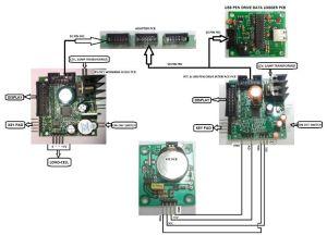
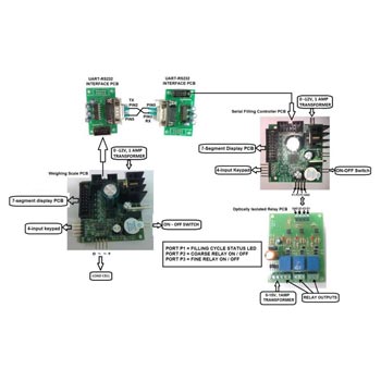
The Controller PCB also provides real time serial weight data as TTL UART output. You can use a RS232 interface adaptor for interfacing with PC. For more information regarding calibration & settings of the weighing & controller PCB, please call the manufacturer.
Weight Range
| Weight Range | Relay-1 State | Relay- 2 State | Relay-3 State |
| 0 to set 1 Value | ON | OFF | OFF |
| Set1 to set 2 Value | OFF | ON | OFF |
| Greater than set 2 Value | OFF | OFF | ON |
