raghu@isysindia.com View Mobile Number
| Business Type | Manufacturer, Supplier, Retailer |
| Caution | Wrong connection may damage the RTC |
| Quality | Superior |
| Condition | New |
| Click to view more | |
Product Details
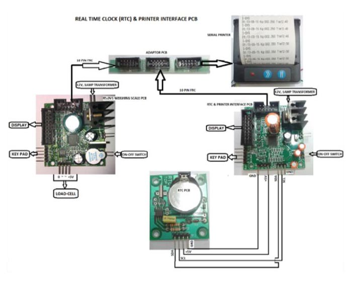
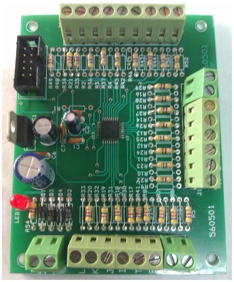
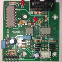
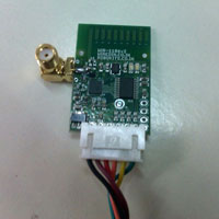
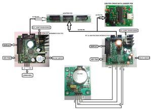
The RTC & Printer Interface PCB is connected to R5.0V1 weighing scale PCB & a serial printer via an adaptor PCB using 10pin FRC cable. The Real Time Clock (RTC) PCB is connected to this board as shown in the schematic above. Make sure the +5V, ground, SCL, SDA pins are connected as per diagram. Wrong connection may damage the RTC.
The RTC & Printer Interface PCB reads the weight data (from R5.0V1 PCB) & time data (from RTC PCB) simultaneously. This time stamp is printed out on the serial printer if ENTER key(K1) on this board is pressed. This data can also be sent to a PC via RS232 interface card not shown in the diagram. Useful header data like address or slogans can be entered & stored in the EEPROM of the RTC & Printer Interface PCB. This information may also be printed along with time stamp. The customer has to enter the ascii value of the header data by looking into a ascii table. For more assistance contact the manufacturer.
Microcontrollers & RTC used
- R5.0V1 weighing scale PCB – Renesas 16bit microcontroller.
- RTC & Printer Interface PCB – ST Microelectronics STM8S 8 bit controller.
- RTC PCB – RTC Chip – NXP(Philips) PCF85163
Configuring The RTC & Printer Interface PCB
To configure the PCB, connect the power supply. Now press Key(K4) and with the key(K4) pressed power on the Machine (ON-OFF switch connected to the PCB).
It shows
| t | I | n | n | E | . |
This is for setting the time in RTC Chip. Now press the Enter Key(K1). It will show
| Y | r | S | - | 1 | 5 |
This means years. Enter the year say 15 as shown…
By using Increment (INC) Key(K2) & Shift Key(K3). Press Enter Key(K1) to accept the data.
Next it will blink & show…
| n | n | o | n | 1 | 2 |
This means month. Enter value (1 to 12) using the INC Key(K2) & SHIFT Key(K3). To accept the value press ENTER Key(K1).
Next it will display day…
| d | A | Y | - | 5 |
You can enter(0 – 6). Enter “0” for Sunday, “1” for Monday & so on. Select the appropriate day value & press ENTER Key(K1).
Next it will display date
| d | A | T | - | 1 | 0 |
You can enter(1 – 31).
Next it will display hours….
| H | r | S | - | 2 | 3 |
You can enter(0 – 23).
Next it will display minutes….
| n | n | I | n | 5 | 9 |
You can enter(0 – 59)
Next it will display seconds….
| S | E | C | - | 5 | 9 |
You can enter(0 – 59)
Press ENTER Key(K1). You have successfully set the RTC clock & your clock will start running from the time you have entered.
The display returns back to time menu & will show….
| t | I | n | n | E | . |
Now Press INCREMENT Key(K2). It will show….
| C | O | n | n | . |
This means UART communication settings.
Press ENTER Key(K1). It will show….
| b | A | U | d | 0. |
You can enter values (0 – 1). Enter “0” for 9600 bauds (Default) or “1” for 2400 bauds. Press enter to accept the value.
Next it will return back to communication menu & display….
| C | O | n | n | . |
Next press INCREMENT Key(K2). It will show….
| H | E | A | d | E | r. |
This means Header data you can store in EEPROM for printing.
Press the ENTER Key(K1). It will blink & provide space for you to enter asci value.
| 0 | 6 | 5. |
Example: Enter “65” for printing character “A”. You can down load asci chart from the internet & use it to enter & print your own text data. Ascii values(0 – 127) can be entered. A total of 90 ascii characters can be stored & printed. If you want to enter only 10 characters, just enter the 10 characters one by one & then switch OFF & switch ON the PCB. There is no need to enter all the 90 characters. Value “0” is null character & nothing will be printed.

